The next next generation of wireless digital intercoms is eclipsing analog. And for good reason; digital systems support a larger number of beltpacks, simultaneous communication, and software integration. Coms like Clearcom’s Tempest line embody these benefits and deliver exceptional wireless performance. However, when problems do arise, their causes and fixes sometimes differ from those in analog systems. This post discusses three of the most common wireless complications in digital intercoms, and methods for addressing them.
Digital intercoms work by sending “packets” of digital information across a wave in a pattern that replicates an analogue signal. For those familiar with analogue modulation, the carrier wave is modulated by bits of information with amplitudes that follow the general contour of the wave, instead of another analog wave.
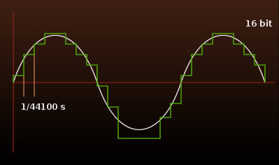
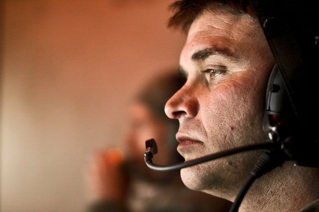
Image courtesy Pawl Zdziarski.
With intercoms, both base stations and beltpacks are equipped with instructions on arranging and decoding these packets into usable audio. Low or overlapping signals, and therefore lost or corrupted packets, often manifest as jitters or significant delays and echoes in the audio as the packets build up and are redelivered, or fail to deliver.
Antenna coverage overlap.
We spoke with Mike Motes of Channel D Solutions, an intercom consultation firm that designs Tempest accessories and optimizes multi channel com systems in large venues. Director of technology Motes says that it’s important to remember using antennas to improve reception on analog systems is different from using them on digital. “The biggest issue that we face with users coming off an analog system, is that people will say ‘oh, we need coverage here, we’ll just throw up another antenna.’ In digital it doesn’t always work that way. They [digital coms] have installed packets, so you inherently have a longer time delay, whereas with analog it’s almost instantaneous.”
Mike is talking about latency: the total time it takes a signal to travel from its point of origin to its destination. In digital equipment, latency is longer, since the signal travels through components that encode analogue audio into digital bits, and then back again.
“If you throw another antenna up,” Motes continues, “and its in range with the first, the beltpacks can actually get confused because the signal is arriving with a slight time differential. That causes what we call symbol corruption and you’ll actually lose packets of audio.”
Channel D carefully manges the placement of external antennas to avoid these types of digital losses. “What we do is plot on the floor plan the coverage of the antenna, then move to the next area and find out where that overlap zone is. You can actually shoot yourself in the foot by having too many antennas. It’s not a matter of pumping more power and getting more gain, it’s about using a little bit of power in the right places.”
Multi-path interference.
Digital packet corruption from multi-path interference is caused by the same situation as coverage overlap--signals arriving at the receiver at slightly different times. But the time differential is caused by different portions of the wavefront taking different paths to the receiver, instead of two wavefronts arriving from two sources placed at two different distances.
Wireless digital intercom systems are fundamentally more susceptible to multi-path because they require sequential pieces of information delivered in the proper order to reassemble the audio intact. Lose just a few of these pieces and decoder performance will suffer. Thankfully, modern systems are equipped with onboard error correction software that compensates for lost packets.
But error correction does have its limits, says Motes. “If you have an area where too many reflections are arriving, even if they are close in time and/or phase, you will still have data corruption. An example of this is a closed-dome stadium, where there is a lot of metal used in the dome. It provides for a near-perfect environment for multipath to take place.”
Popping and drop-outs.
Most high-end digital intercoms, like the Clearcom Tempest 2400 and 900, use frequency hopping technology to avoid interference. The beltpack and receiver constantly jump in tandem from one frequency to another, identifying which channels are full and avoiding them the next hop around.
Some 2.4 GHz intercoms, although rarely products in the Tempest line, create sharp popping sounds when they briefly encounter Wi-Fi or other sources of interference on one of the channels they are hopping through. Eddie Gonzalez, senior audio engineer at Multi Image Group, spoke to this concern. “Usually at shows with huge convention floor spaces you'll get noises a loud click or pop, either they’re dropping out, or people get out or range. It’s my biggest issue.”
This may be mitigated by switching to an antenna of greater selectivity, increasing range and tuning out the competing signals. Circularly polarized helical antennas in particular are effective tools for combating these pops. In addition to directionality, the circular polarization of the helical design helps cut down on changes in polarization caused by phase shifts when the wave reflects off a surface.
We recently released a 2.4 GHz helical antenna, and although we did not design it specifically for the intercom market, we were pleasantly surprised to hear that Eddie used it with great success to eliminate these popping sounds and increase working range, too. If you’re using a 2.4 GHz digital intercom, please consider contacting us for a demo.