
These five common concepts and skills separate the skilled audio professional from the beginner.
In our opinion, they are essential to a full understanding and mastery of audio systems.
They are evenly divided between simple overarching concepts that can be applied to any project, and practical skills that can be used to save time and money, or engineer elegant solutions to problems that emerge in the field.
1. How to coil cables right.
Many types of audio-visual cables contain twisted wires inside a sheath. This gives them a natural coil that can easily be disturbed by improper coiling. The wires become tangled inside the sheath, and the natural coil ruined, shortening the cable’s life. Other types of cable, like coaxial cable, have no natural coil. They still benefit from proper handling, which avoids knots, tangles, and crushed insulators.
The right way to coil a cable is by using the “over-under” method, which is better shown than explained. This video from the London School of Sound does an excellent job showing how to coil cables using the over-under technique.
[youtube https://www.youtube.com/watch?v=pEd7ru24Vx0]
2. How to build cables from scratch.
Many audio cable connector schemes follow a basic blueprint: positive, negative, ground. If you know how to strip and make a connection from raw cable, you can build cables to custom lengths and salvage good portions of damaged cable - which is incredibly useful. Although the specific procedure for soldering a connector varies by type, a soldering station (iron, sponge, solder, helping hands), box cutter, and pliers with wire snips are often all that is required to solder the more common types, like XLR, ¼”, and 3.5mm, during an emergency repair.
For best results, and to avoid damaging equipment, do a little research on the construction and connection design for each type of cable and connector, and use specialized strippers and fabrication tools for routine or bulk cable work. This document from Suffolk County Community College does a great job explaining how to make ¼” and XLR cables. If you’re new to soldering, Smith College has a great guide and collection of resources here.
RF connectors for use with external antennas, like BNC and N connectors on 50 ohm coaxial cable, must be treated with additional care. They must be properly terminated and impedance matched to prevent signal loss or radio reflections, which aren’t as relevant when dealing with audio cables. Ideally, an RF termination is tested afterwards using some sort of cable or network analyzer to verify the connection across a range of frequencies. A basic guide to terminating coax with a BNC connector is here, courtesy Del Mar College.
3. Ohm's law.
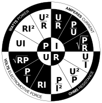
This one is not exactly a "how to," but it is still extremely important. Audio systems pull heavily from electrical engineering. Electricity is a complicated topic, but one of its most practical rules - Ohm's Law - is not.
To understand Ohm's law, you need to know three concepts: voltage, current, and resistance.
Voltage is the measure of electrical potential energy. Voltage motivates electrons to move across the surface of a conductor, but it does not describe the movement itself - only the potential for movement, or “pressure” as is often invoked when comparing electricity to water in a pipe. The unit of measure for voltage is the volt.
Current is the number of electrons that move through a conductor during a period of time. It is a measurement of electron flow. The unit of measure of current is the ampere.
Resistance is the likelihood of a material to offer up a free electron to its neighbor. Electrons within a conductor move by hopping from one electron orbit of an element or compound to another. Resistance is measured in ohms.
Ohm's law simply states that current is directly proportional to voltage, if resistance is constant.
Current = voltage/resistance
Wrap your head around that and you can algebraically derive voltage, current, and resistance if you have any other two - and you have the foundations for understanding basic circuits and many other types of simple electrical devices.
For example, if a wire with a resistance of 3 ohms creates a circuit across the negative and positive terminals of a 9 volt DC battery, we have the voltage and resistance values we need to find current. In this case, the current equals 9/3, or 3 amps. Bump the voltage up by 100%, and the current will rise proportionally. Current will be 6 amps if 18 volts is divided by 3 ohms.
[youtube https://www.youtube.com/watch?v=CH0NyRCpAZ4?list=UUM-kjdrQge9AACfB3MSRyrg]
4. How to use a multi-meter.
Now that you know all about Ohms law, I bet you wish there were some sort of magical device that could tell you voltage in a battery or power source, current in a circuit, or the resistance of a wire. There is! It’s called a multi-meter.
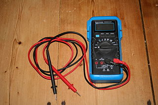 Image courtesy Andrew Fogg.
Step by step instructions on how to use a multi-meter are too detailed for this post. But with an understanding of Ohms law and your meter’s instruction book, you can be up and running in a few minutes. There are also numerous online tutorials for using the device.
Multi-meters aren’t just for tinkerers and engineers. A multi-meter is an indispensable tool for tracking down problems with cables. As we heard from the worlds best monitor engineers in this post, bad cabling is an all too common culprit of signal problems. Sometimes, damage to cables is invisible. Cables may also be functional, but not at peak performance. One way to gauge an underperforming cable is to check its resistance. The quickest way to diagnose a failed cable (that creates a short circuit) with no visible signs of damage is to use the continuity function of a multi-meter, which we do in the following video. In this case, the ohm-meter (one of many tools on a multi-meter) does not reveal a short circuit, because there isn’t one. Instead, we use the multi-meter to demonstrate just how fragile coaxial cable can be - but the demonstration of the multi-meter is still useful.
5. How to set gain structure.
Gain structure is the management of voltages between signal stages to maximize signal-to-noise ratio, and avoid audio overloads, distortion, and noise. Setting levels on any audio device in the signal chain changes the voltage that is output to the next device. Levels need to be carefully managed because they have the potential to upset the electrical balance in the entire system. Synaudcon has a great 5 minute overview of what gain structure is and why it’s important. Their other training materials are much more detailed and worth a look.
Unity gain is the textbook practice of ensuring that the same voltage output is maintained between every intermediary step between the microphone and loudspeaker. In fixed signal chains using simple audio modulation, unity gain is a must.
But when frequency modulated wireless microphones are introduced, unity gain is not as important in the wireless portion of the pathway. In fact, we argue that too much fuss about unity gain between the transmitter output and receiver input is much ado about nothing for the majority of users. Take a look at a video we did earlier this summer on the topic, which dovetails with Synaudcon’s explanation of gain structure.

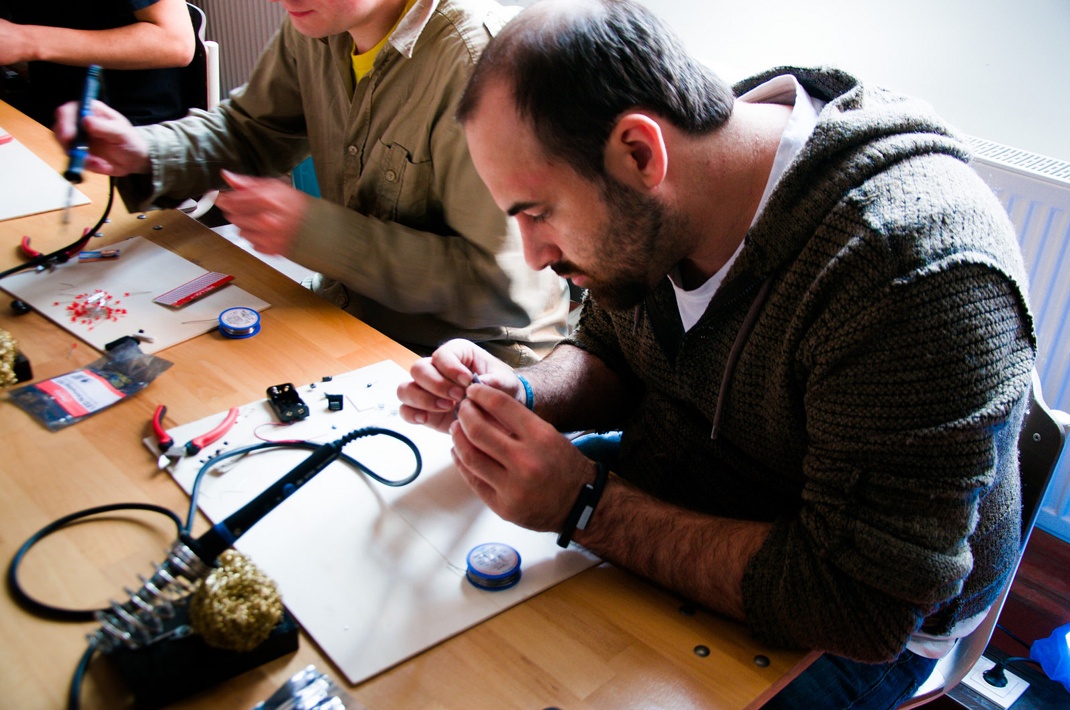
Leading image courtesy Mitch Altman.