
A radio wave is composed of one electric and one magnetic field that oscillates in a repeating pattern. Polarization describes the way the electric field of the radio wave is oriented. In some cases, especially waves that are generated by a natural source, the fields vibrate in multiple random orientations, and are said to be unpolarized. But when waves are generated from, or passed through an intentionally polarizing device, such as an antenna, the fields are restricted in movement and are said to be “polarized.”
Wave polarization is not a particularly easy concept to visualize. It takes place in three dimensions and across time. Polarized waves have a fixed, constant orientation and create a path that is shaped like a flat plane as it travels through space, and have what we refer to today as linear polarization. The first 40 seconds of this video show linear polarization.
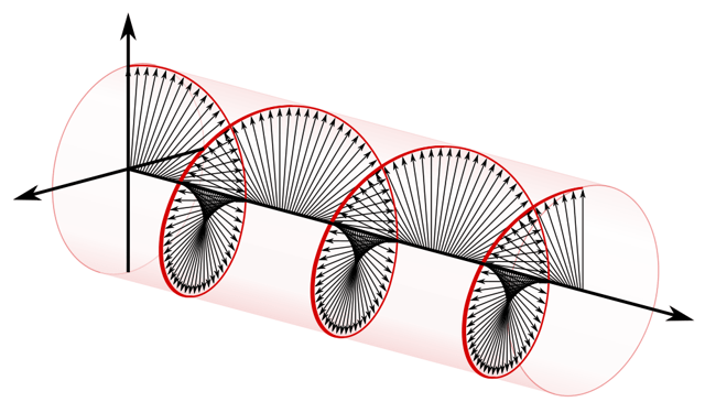
There can also be circular polarization, which, unlike in linearly polarized radio waves, the electric field also spins along an axis, sort of like a twisted ribbon. The final half of the video demonstrate this.
The more common antenna types are linearly polarized, like dipoles, whips and LPDAs. But you won’t hear the term linear polarization thrown around at an equipment store. Instead, we get some antenna terms from the linearly polarized types: when the linear plane is perpendicular to the ground, it is said to be vertically polarized. When that plane is parallel with the ground, it is horizontally polarized. But really, these terms are arbitrarily based on the human perception of up or down in relation to the earth and gravity, not some physical constant.
In general, it’s better to keep the orientations of the two antennas matched. Reception is best when the receiving antenna is not in a position that prevents the polarization from being too far off from the transmitting antenna, though it rarely needs to be exact.
Helical antennas are the most frequently seen circularly polarized antennas in the pro sound world. “Helicals” can produce a circularly polarized beam with high gain by using a carefully modeled spiral construction that produces either right handed (clockwise spin), or left handed (counter clockwise) polarization to the signal. Helicals are useful as a receiving antenna, since they pick up incoming waves of any polarization to the same degree. Shifts in orientation from a handheld or beltpack transmitter are less likely to cause the drop-outs which very often happen when a performer moves to a less favorable polarization.
Even though polarization is initiated predominately by the transmitting antenna, radio wave polarization can change dramatically when reflecting off objects in the environment, such as walls and floors. The result is uncertainty about which orientation a particular radio wave will be when it reaches the receiver antenna, and there is always a chance that a condition called “crossed polarization” will occur: When that happens, a noise burst is briefly (but noticeably) heard. No one wants that. To avoid crossed polarization fades, you can use a technique known as polarization diversity by orienting two antennas closely together, but oriented 90 degrees from each other.* This makes it very likely that a given radio wave will be picked up by at least one of the antennas at all times.
*RF Venue has incorporated this little known technique in the Diversity Fin antenna. Read more at Mike Benonis’ paper. Video courtesy of "Ruff."